Note: There is an updated (simplified) version of this project here.
Background
This problem was presented by a colleague of mine – he does a lot of home brewing and needs to keep his yeast starters agitated. “A stir plate helps you culture higher cell counts of healthy yeast for quicker fermentations, lower risk of infections and better tasting beer.”, apparently.
Solution
Magnetic stir plates are a thing, they can be bought from around £40 and many also include a heating element. That said, building your own sounds like more fun. The internet includes many tutorials on building a DIY stir plate using a PC fan and some neodymium magnets, we’re simply going to take it up a notch by using PWM to control the fan speed and (hopefully) report back the actual speed of the fan, as a proxy for the stirring speed.
Total cost = £27.49 but in reality, you can scavenge many parts (e.g. fans, psu) and many parts are available cheaper in bulk (magnets, knobs etc) which will bring down the parts costs considerably.
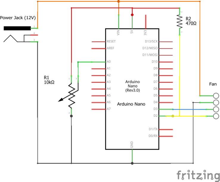
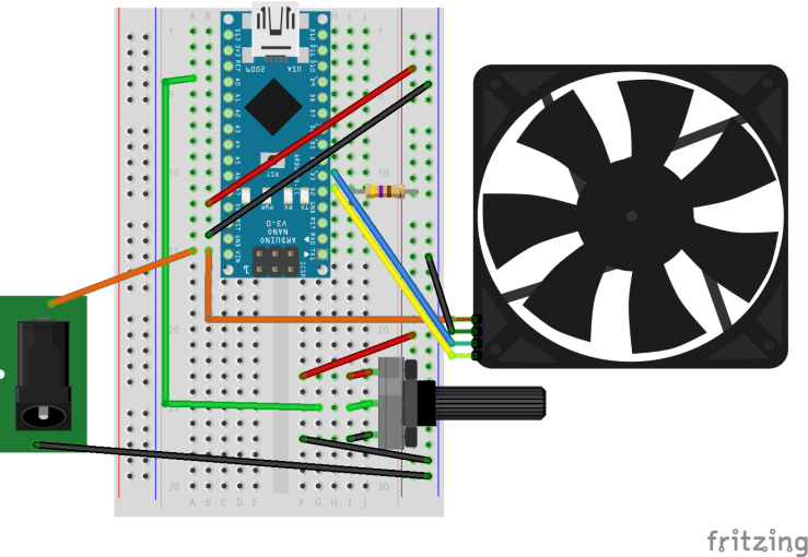
Diagrams
Note, the 4 Digit display has not yet been included in the below diagrams.
So far this prototype is unfinished, the project box and the magnetic stir bar are both waiting to be delivered so no pictures of the final article yet. I’ll update this article with more details when it’s finished.
I’ve also learnt that 2.5mm x 5.5mm barrel plugs sometimes fit in 2.1mm x 5.5mm barrel sockets, but not reliably and can cause intermittent power issues. I’ll be standardising on 2.1mm x 5mm in future as this seems to be more popular (e.g. used on the arduino) .
Sous-Vide is a cooking method involving precise temperature control. A temperature controller of some kind (usually a PID controller) is usually required. The Souse Vide Supreme is one such controller integrated with a water bath.
I have in my posession a broken sous vide supreme. I knew it was broken when I bought it, but I figured that worst case, I can use the water bath with my existing PID controller (I’m currently using it with a cheap deep fat fryer, but some of the clips are rusting). The symptoms are that the temperature is permanently reading 200 degrees C. Otherwise the unit seems to be working correctly (I’ve not yet proved that the heating circuit working as it never kicks in, believing the temperature to be always higher than the set point).
Step 1. Take it apart – that I’ve managed, but I didn’t take enough pictures. From memory the hardest part was reaching some of the nuts. There were no obviously visible faults, all cables look fine and no components are noticably burnt out. It’s interesting to note that most of the components are through-hole which should make debugging a bit easier.
Step 2. Check the thermistor – It’s plugged into the board with a socket, making it very ewasy to remove. Sadly (as it’s would have been an easy fix) it seems to be working fine. At room temperature a voltmeter reads the resistance at close to 100k Ohms, this drops noticeable when I warm it between my fingers. It appears to be a glass encapsulated 100k Ohm NTC thermistor in working order.
LM258AP Dual Op Amp in souse vide supreme circuit
The thermistor is wired up to an LM258AP op amp. I’ve done a bit of reading and I assume the op amp is there to amplify a signal from the thermistor in preperation for passing to an ADC. Step three will be to analyse the circuit to see if I can confirm that this is how the op amp is being used, then attempt to test the op amp. Feel free to give me any advice in the comments, circuit debugging is not my area of expertise!
The idea is to take apart a relatively cheap cordless drill and use the motor as a mains powered gear motor with arduino speed control.
Step 1. Dismantle a drill.
I happened to have this drill in the junk box because the battery was no longer holding it’s charge. The motor was working perfectly fine. I considered keeping the speed control circuit and direction switch but dismantling them to see how they worked left me with a pile of bits and a few lose springs.
The useful bits to keep are the motor (with attached gearbox and chuck) and the MOSFET (with attached heatsink).
It would help at this stage if you label the Gate Source and Drain legs of the MOSFET.
Step 2. Prove the motor working.
First thought was to plug it into a low voltage (5V) high current (2A) switch mode mains adapter. All this did was cause the adapter to cut out. It turns put that the motor is an inductive load so Ohm’s law doesn’t help much. Googling seems to suggest this type of motor quite easily draws 20A – far too much for any adapter I have lying around.
So, prove the motor working by connecting it to the battery. It doesn’t matter which way around. Careful it doesn’t jump off the desk as it’ll spin at it’s top speed.
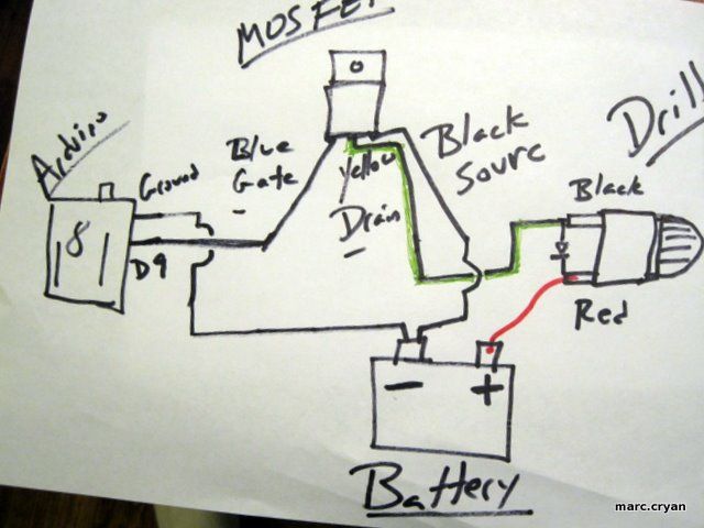
Step 3. Connect up the MOSFET.
The following diagram found on Instructables was a great help here:
Marc Cryan’s motor control diagram – great help!
I include my own circuit diagram which may or may not be clearer:
Battery driven motor circuit, on off switch control
At this stage I’ve left out the arduino as it’s worth checking the MOSFET is wired in the correct way before proceeding (I got it wrong first time). Instead the diagram includes a switch – two wires that can be touched together works well.
Closing the switch should cause the motor to spin at it’s top speed. I didn’t run it like this for long as I really don’t know what good it does to the MOSFET.
Step 4. Program the arduino.
Now is a good time to make sure the arduino can be programmed and works correctly. I include here a basic sketch which allows the PWM duty cycle on pin 3 to be set by sending a single ASCII character over serial.
int motor = 3;           // the pin that the motor is attached to, this
                         // can't be changed without changing pwm code below
int inrush_speed = 255;  // start on max to overcome inrush current
int inrush_delay = 100;  // time in miliseconds required to overcome inrush
int default_speed = 30;  // returns to this speed after inrush
int incomingByte;        // for incoming serial data

void setup() {
  // declare motor pin to be an output:
  pinMode(motor, OUTPUT);

  // Set up high frequency PWM
  TCCR2A = _BV(COM2A1) | _BV(COM2B1) | _BV(WGM21) | _BV(WGM20);
  TCCR2B = _BV(CS00);

  // Set up serial port
  Serial.begin(9600);     // opens serial port, sets data rate to 9600 bps
  Serial.println("READY");

  // Start the motor spinning with a high speed
  analogWrite(motor, inrush_speed);
  // For a short amount of time
  delay(inrush_delay);
  // Now initialise motor at a sensibly slow speed
  OCR2B = default_speed;
}

void loop() {
  // do something only when you receive data:
  if (Serial.available() > 0) {
    // read the incoming character as a value:
    incomingByte = Serial.read();
    // write it back out:
    Serial.println(incomingByte, DEC);
    // set the motor speed to the ascii value
    OCR2B = incomingByte;
  }
}
Note that I’m not using analogWrite here since i found the 490Hz pwm signal resulted in the motor whining at low duty cycle. Instead I’m using the timers directly with no prescaler to get a much higher frequency pwm signal.
Once the sketch is loaded, attach an led and suitable resistor to pin 3, bring up the serial console and send a few characters. If all’s gone well you should see the led brightness change as different characters are sent. The arduino should send back the code for each character as you send it. An ASCII lookup table will help you predict the brightness of each character.
Step 5. Connect arduino to motor circuit.
Thus is an easy step, just connect the gnd pin from the arduino to the negative terminal on the battery, remove the led and associated resistor, then connect pin3 in place of the switch. I include an updated circuit diagram:
Battery powered, arduino controlled motor circuit
It’s worth mentioning at this point that the most the arduino can push out on pin 3 is 5V. This means that the drill can’t be driven at full speed in this scheme. If you wish to be able to run the drill at full speed I believe you can use a resistor to pull the gate high (to the battery high voltage) then connect the arduino to a transistor that when closed pulls it low. I haven’t tried this though.
The current behaviour is fine for my purposes and probably a requirement if you’re running from an underpowered adapter as I am. Speaking of which:
Step 6. Connect mains adapter.
I used the adapter that was previously powering the battery charger, rated to a slightly higher voltage than the battery was rated. Now that the arduino is ramping down the voltage it ‘just works’, with one caveat: the motor would only start with a fairly high (20%) duty cycle. This was not ideal, so to overcome it I included in the sketch above some code to make the initialisation speed very fast but only for a few milliseconds. In practice this is not noticeable. I haven’t checked the current usage on startup but I assume there’s a moderate spike – it’s not caused me any problems though.
Opening the case was not straight forward (probably a good thing for weatherproofing). There is a small piece covering the wire connections which simply lifts off (it was held on with hot glue) but the rest is pretty much welded shut. I ended up cutting it open with a junior hacksaw.
It’s worth noting here that if you do want to weather proof this unit fully, the hot glue for the wire connections was pretty sparingly applied on my unit. I’d recommend removing it and replacing with liberal amounts of hot glue (I doubt silicone would stick well to this plastic).
I neglected to take a shot of the case before attacking it with the saw (check out the amazon shots from my mini review if you really care) so I’ll dive straight in with some photos of the circuit:
A shot of the drive circuit.And a shot of the traces.
There’s actually two resistors on the board but you can’t really tell from the angle the first shot was taken. To make things a bit easier to read I’ve attempted to draw out the circuit. Apologies for the symbols used to represent the SCRs, CircuitLab doesn’t have a Thyristor symbol I’m afraid. Also note that D5-D8 each represent a set of 75 LEDs and resistors R3-R6 are not an accurate representation (I’ve spotted a few resistors on the strings, but neither counted not measured them).
LED String circuit diagram
Before I go any further I want to talk to you about flicker. If you read my previous post you’ll know that although these LEDs are full wave rectified (note diodes D1-D4 make up a bridge rectifier) there is still a noticeable flicker as these lights move across my vision.
A video does very little to demonstrate this flicker as the frame rate of the video is far too low to capture it, so instead a longi(ish) exposure can be taken with the LED moving relative to the camera, as show here:
1/10th second exposure of single bulb from LED string on the left, reference light (from my iphone) on the right.
This shot was taken with an exposure length of 1/10th of a second. The first thing to notice that the line of the left (a single LED in the string) is dashed, while the reference LED is not. The string was set to ‘always on’ so the dashes are not the result of a programmed blinking pattern, instead it’s a result of the unfiltered full wave rectification.
To make this more obvious we can calculate the frequency at which the LED is blinking. There are 10 dashes and the exposure was 1/10th of a second, so there’d be 100 dashes in one second, hence a frequency of 100Hz. AC around here is 50Hz and full wave rectification results in doubling the frequency, so 100Hz as expected.
The next thing we can see is the duty cycle. I haven’t taken a ruler to the shot, but the dashes are around twice the length of the gaps in between, so the LEDs are on for 2/3rds of a cycle or around 66%. I’m sure you’d agree that’s quite a lot of info that can be gleaned from a single photo!
I had initially (before tearing apart the case or taken the long exposure shot) assumed the flickering was due to half-wave rectification. So much so that on the weekend I bought four rectifier diodes to add my own bridge rectifier. It was quite a surprise to tear open the case and find four identical diodes already in situe.
The next plan was to add a capacitor after the bridge rectifier to smooth out the bumps. I realise now though that this approach would not be very successful either. The problem (one of many I’m sure) lies in the PCR406 SCRs. The wikipedia article on Silicon Controlled Rectifiers kindly explains that these can be thought of as latching switches, once they’re switched on they stay on, until the current through them drops below the latching current.
With a flat DC supply (as I would get by adding a smoothing capacitor) this means the nice twinkling effects which I was hoping to keep would no longer work. It works in the current set up because the DC signal is dropping to zero 100 times a second, so although the SCRs latch, they are only held on for at most 1/100th of a second.
The plan now is to add a smoothing capacitor, but on a slide switch – if the switch is off the capacitor is kept out of circuit and the lights work as though unmodified. If the switch is closed, the smoothing cap does it’s job, the SCRs remain always latched and the lights should run constantly on with no flicker. That’s the theory anyway, of course they may not light at all, some experimentation is called for!
Finally some further reading, if nothing else these may give you an idea of where I get all my info from:
Oh, and the obligatory warning: Caution! Circuit is lethal since it carries high voltage AC. Do not touch or test when connected to Mains. There, done.
I recently bough a string of 300 warm white LED fairy lights from Proxima Direct. These lights were given great reviews on amazon and are pretty cheap at around £20.
I won’t go in to a full review (what pictures I have are ‘borrowed’ from the amazon site) but here are a few things to note should you be considering buying these:
Good points:
They are full wave rectified
The ‘warmness’ of the LEDs is nice, about the same as a warm CFL
They have eight settings for flashing and dimming, I especially like the ‘twinkling effect
Bad points:
Despite the full wave rectification the though there is a 100Hz flicker even when fully on
A set bought by my collegue had every fourth LED dead, so there are obviously some quality control issues
There is not memory for which setting you had selected before switching them off and constant-on (my preferred setting) is last in the list
The water proofing at each LED is dubious – no doubt they’d last outside for a while but I suspect after a month or two you’ll have problems
All things considered I think they’re great value for money. My plan is to fix the 100Hz flicker (It’s noticable, but only when they move across my line of vision) and probably improve the water proofing so that I can put these lights outside permanently.
Stay tuned for the next post which will include a teardown, analysis of the flicker (I’ll try and deduce the duty cycle) and some investigation of the driving circuit.
 Background