Opening the case was not straight forward (probably a good thing for weatherproofing). There is a small piece covering the wire connections which simply lifts off (it was held on with hot glue) but the rest is pretty much welded shut. I ended up cutting it open with a junior hacksaw.
It’s worth noting here that if you do want to weather proof this unit fully, the hot glue for the wire connections was pretty sparingly applied on my unit. I’d recommend removing it and replacing with liberal amounts of hot glue (I doubt silicone would stick well to this plastic).
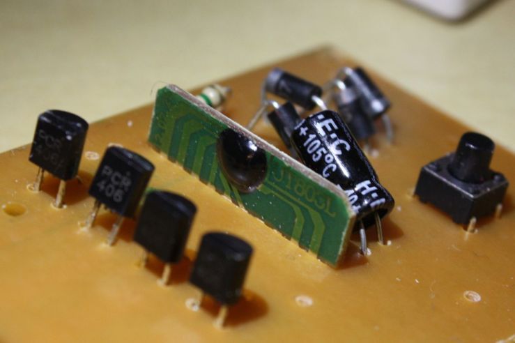
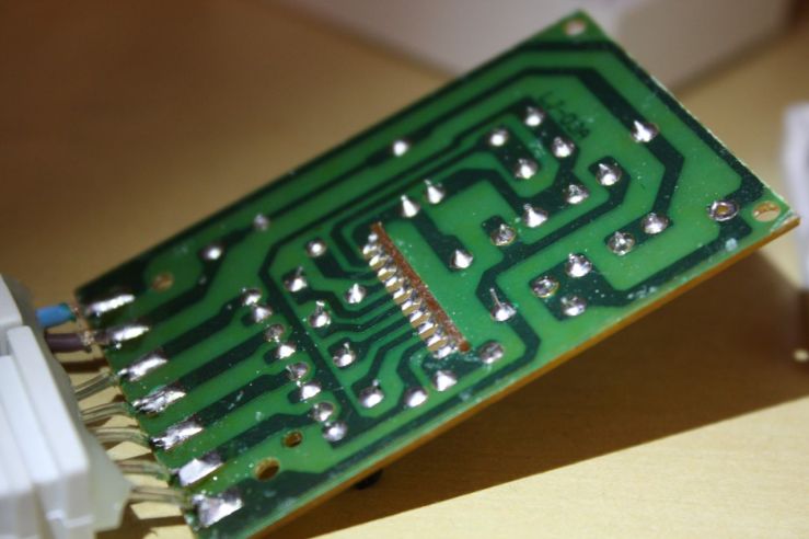
I neglected to take a shot of the case before attacking it with the saw (check out the amazon shots from my mini review if you really care) so I’ll dive straight in with some photos of the circuit:


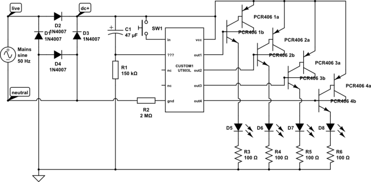
There’s actually two resistors on the board but you can’t really tell from the angle the first shot was taken. To make things a bit easier to read I’ve attempted to draw out the circuit. Apologies for the symbols used to represent the SCRs, CircuitLab doesn’t have a Thyristor symbol I’m afraid. Also note that D5-D8 each represent a set of 75 LEDs and resistors R3-R6 are not an accurate representation (I’ve spotted a few resistors on the strings, but neither counted not measured them).

Before I go any further I want to talk to you about flicker. If you read my previous post you’ll know that although these LEDs are full wave rectified (note diodes D1-D4 make up a bridge rectifier) there is still a noticeable flicker as these lights move across my vision.
A video does very little to demonstrate this flicker as the frame rate of the video is far too low to capture it, so instead a longi(ish) exposure can be taken with the LED moving relative to the camera, as show here:

This shot was taken with an exposure length of 1/10th of a second. The first thing to notice that the line of the left (a single LED in the string) is dashed, while the reference LED is not. The string was set to ‘always on’ so the dashes are not the result of a programmed blinking pattern, instead it’s a result of the unfiltered full wave rectification.
To make this more obvious we can calculate the frequency at which the LED is blinking. There are 10 dashes and the exposure was 1/10th of a second, so there’d be 100 dashes in one second, hence a frequency of 100Hz. AC around here is 50Hz and full wave rectification results in doubling the frequency, so 100Hz as expected.
The next thing we can see is the duty cycle. I haven’t taken a ruler to the shot, but the dashes are around twice the length of the gaps in between, so the LEDs are on for 2/3rds of a cycle or around 66%. I’m sure you’d agree that’s quite a lot of info that can be gleaned from a single photo!
I had initially (before tearing apart the case or taken the long exposure shot) assumed the flickering was due to half-wave rectification. So much so that on the weekend I bought four rectifier diodes to add my own bridge rectifier. It was quite a surprise to tear open the case and find four identical diodes already in situe.
The next plan was to add a capacitor after the bridge rectifier to smooth out the bumps. I realise now though that this approach would not be very successful either. The problem (one of many I’m sure) lies in the PCR406 SCRs. The wikipedia article on Silicon Controlled Rectifiers kindly explains that these can be thought of as latching switches, once they’re switched on they stay on, until the current through them drops below the latching current.
With a flat DC supply (as I would get by adding a smoothing capacitor) this means the nice twinkling effects which I was hoping to keep would no longer work. It works in the current set up because the DC signal is dropping to zero 100 times a second, so although the SCRs latch, they are only held on for at most 1/100th of a second.
The plan now is to add a smoothing capacitor, but on a slide switch – if the switch is off the capacitor is kept out of circuit and the lights work as though unmodified. If the switch is closed, the smoothing cap does it’s job, the SCRs remain always latched and the lights should run constantly on with no flicker. That’s the theory anyway, of course they may not light at all, some experimentation is called for!
Finally some further reading, if nothing else these may give you an idea of where I get all my info from:
- Examination of a similar half wave rectified set
- Video review demonstrating duty cycle using a meter (17:55) and an oscilloscope (9:07)
- Using a DSLR camera to determine the frequency of a blinking LED
- An explanation of the principles behind a transformerless power supply (it turns out that these lights do not use this principle, it’s still an interesting read though).
Oh, and the obligatory warning: Caution! Circuit is lethal since it carries high voltage AC. Do not touch or test when connected to Mains. There, done.